Comparison of numerical results of bone remodelling and clinical observations in short-stem hip-jointprosthesis
2 Volkswagen AG, 38436 Wolfsburg, Germany
3 Department of Trauma and Orthopaedic Surgery, Städtisches Klinikum Braunschweig GmbH, Holwedestraße 16, 38118 Braunschweig, Germany
4 Institute of Mechanics and Computational Mechanics, Gottfried Wilhelm Leibniz Universität Hannover, Welfengarten 1, 30167 Hannover, Germany
Received: 11-Nov-2017 Accepted Date: Dec 04, 2017 ; Published: 06-Dec-2017
This open-access article is distributed under the terms of the Creative Commons Attribution Non-Commercial License (CC BY-NC) (http://creativecommons.org/licenses/by-nc/4.0/), which permits reuse, distribution and reproduction of the article, provided that the original work is properly cited and the reuse is restricted to noncommercial purposes. For commercial reuse, contact reprints@pulsus.com
Abstract
Background: Investigations of the density distribution of bone caused by implants make predictions in bone remodelling possible. For the execution of these analyses, a method is presented with finite element calculation.
Methods: A biophysical model based upon a finite-element calculation is examined with numerical calculations of short-stemmed (Mayo and Spiron), uncemented prostheses. Changes in bone mineral density -- measured over a period of 5 years in 100 patients after total hip replacement, -- were used as reference for the quantitative check calculations. The developed algorithm underlying these FE-calculations was subjected to an application test, and both an approved and new short-stemmed artificial limb system regarding its density distribution is simultaneously examined.
Results: The spiron-system was found to have the lowest resorption behaviour.
Conclusions: For the short-stem prosthesis bone remodelling activity in the area of the medial proximal corticalis is obviously.
Keywords
Finite-elements, Bone densitiy, Stress shielding, Short-stem prosthesis
Introduction
Hip replacement in young patients often leads to a high probability of revision operation later in life [1]. Therefore, the aim already at primary implantation should be to remove few bones, and to obtain a stand time as long as possible. The variety of artificial limb models offered for this indication underlines the fact a solution is yet to be found [2-5]. A commonly used artificial limb is the Mayo hip prosthesis (Zimmer Inc., Warsaw, USA). A newer alternative is the Spiron prosthesis (ARGE, Hannover, Germany), introduced in 2000 (Fig. 1a and 1b). The differences between these two artificial limb types are primarily in construction, overcoating, and implantation technique [2,4].

Figure 1: Mayo prosthesis. (b). Spiron prosthesis.
Measurement of the relative motion between a prosthesis and bone in vitro is the first step in testing the primary stability of a new prosthesis. We did this for the Spiron® prosthesis [6]. She has significantly less motion in the bone/prosthesis interface compared with the Zweymuller prosthesis. While clinical course observation only allows for successful limb implantation to be determined after years, an imminent design problem can be recognized sooner with a numerical calculation. Numerical methods about the adaptation of the bone have been established in previous studies, dating back more than 15 years [5,7-9]. With the help of numerical methods, statements about the change of the bone remodelling are possible without risks for the patient. In connection with this, the question about the validity of the imposed data has been posed [10-12]. In the study presented here, a finite element method is validated with clinical data from bone density analysis of the proximal femur [13], using the method of the calculation of both artificial limb types (Mayo®/Spiron®) [2,14,15]. The aim of the study is to test the principle efficiency and validity of the algorithm, and to obtain results about bone remodelling in artificial limb types.
Methods
Theoretical framework
Computational methods for the simulation of stress adaptive bone remodeling have been under development for more than 15 years. After initial problems with the stability of the algorithms, current methods are stable and efficient methods can be provided. The work presented here is a follow-up to the previous work done by Nackenhorst and colleagues [8,16]. By this approach, the bone is modeled in a continuum sense, meaning that the network structure of cancellous bone in the proximal region of the femur is smeared by an average mass density ρ. However, the trabecular structure can be described with its anisotropic mechanical behaviour [8,17]. Furthermore, due to limited knowledge about time-dependent joint loads and muscle forces, the model is based on statically equivalent forces. These statically equivalent forces are the result of an optimization procedure, which targets the best fit of the computed mass density distribution with the physiological bone. This optimization procedure can be performed for individual anatomy and mobility conditions whenever CT--data are provided. Basic assumption of the theory is an equation of evolution
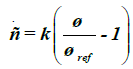 (1)
(1)
that relates the time-rate of mass density to the mechanical demand, which is expressed by the strain-energy density Ψ in the isotropic case. When the strain-energy density exceeds a physiological target value Ψ locally, the bone density increases, otherwise decreasing until each point of the bone is stressed physiologically. It should be noted that this physiological target value is a result of the optimization procedure previously mentioned. Other groups have suggested a tolerance-region around the physiological target value (so called dead zone) [7,9] whereby numerical instabilities can be expected. However, the values suggested are vague, and special numerical treatment is required to prevent the solution from depending on the initial conditions. The parameter k in Eq. (1) is a measure for the time scale in which the remodelling processes take place. This is observed when Eq. (1) is scaled by a reference mass-density ρo,
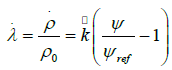 (2)
(2)
where has the dimension of one over time; λ is referred to as design-variable below. Until recently, the time scales in which bone remodelling processes take place were not well investigated, but some guidelines could be derived from fracture healing. This value is of essential interest for remobilization therapies, but it does not need to be specified in this context because only the long term behaviour is of interest for the current investigations. Hence, the time-discretized version of Eq. (2), i.e.,
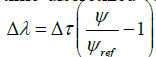 (3)
(3)
will be treated, where a dimensionless time increment has been introduced. The computation of the strain-energy density distribution is performed by a linear-elastic finite element analysis, which is an approximate solution of the mechanical equilibrium for arbitrary geometries under consideration of the specific boundary conditions. A standard procedure leads to a system of coupled linear equations
K u = f (4)
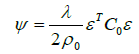
where K is the stiffness matrix, u collects the unknown nodal displacements and f represents the applied external forces acting at the nodes of the finite element model. From the solution, the strain energy-density is derived by a simple post-processing step:
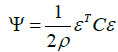 (5)
(5)
where C is the elasticity-matrix and ε the Voigt-representation of the linear strain tensor, which is derived from the displacementfield computed from Eq. (4). It is essential to recognize that the elasticity-matrix depends on the spatial density distribution. A constitutive relation has to be stated between the Youngsmodulus E and mass-density ρ. Within a thermodynamic consistent framework, a relation:
 (6)
(6)
has been proven previously [8]. With the constants E0 and ρ0, reference values (e.g. for cortical bone) have been introduced for a dimensionless representation. Equation (6) is in accordance with a statistical analysis of various independently performed measurements [15]. By combining these findings, Eq. (5) is rewritten as
 (7)
(7)
and therefore, a nonlinear problem consisting of Eqs. (3), (4), (6), and (8) has to be solved. By an explicit approach, the scheme sketched in Fig. 2a has to be solved. Herein, the marker t denotes the incremental step, and the suffix i represents the finite element number. The update loop has to be performed until a convergence criterion is fulfilled; for example, the strain energy and the mass density within the whole system do not change. The real course of the time is not known. It is not clear whether the long-term situation is reached after 6 months or 6 years.

Figure 2a: Explicit solution procedure to the solution of the non-linear problem.
The finite element model has 2625 2D 4-knots planar elemtents (Fig. 2b left) and 32075 3D 4-knots tetrahedron volume elements (Fig. 2a right). The rigidity of the volume elements is variable according to Eq. (6). That means a volume element with a density like zero, has no rigidity and does not exist mathematical. The nets are linked directly to each other, therefore an ideal ingrowth behavior between bone and implant are simulated. The Young´s modulus of these prostheses correspondents to the material properties of titan.

Figure 2b: 2-D and 3-D finite elements net, respectively with load vectors.
The net building was realized with the software “MSC Patran 2001r2”. For the finite element calculation, we used a new algorithm developed with “Matlab 6” [18]. We assume for 3D static aequivalent loads [18], for 2D we assume the one-leg load.
Healthy femur
The first step in numerical analysis performed here is the calculation of the biomechanical balance (Fig. 3). The computed mass density distribution is compared with a radiograph of the proximal femur. The hollow bone, as well as the characteristic trabecular structure of the cancellous proximal femur, is approximated by the finite element model. The medullary cavity, trabecular, and Ward’s triangle can be recognized in the comparison.

Figure 3a: Calculated density distribution of the proximal femur, (b) Comparison with an x-ray image.
Model validation
Validation of the model was executed with data which were investigated from a measurement of the bone mineral density of the proximal femur after cementless hip arthroplasty, over a period of 5 years in 100 patients [13]. The BMD of the proximal femur was measured by DEXA using a QDR Hologic scanner (Hologic Inc, Waltham, Massachusetts). Analysis of the changes of bone mineral density in the 7 Gruen zones of the proximal femur therefore was possible for clinical conditions. As in the cited reference, we used an Alloclassic Zweymüller® SL cementless stem (Zimmer, Inc., Warsaw, USA) for the simulation of change in bone mineral density, and a comparison of estimations with the data [13] was executed. In this model, computed density of the finite elements was added in each Gruen zone. To compare this data with the examinations in [13], the relative change of BMD (compared with the base data) of each Gruen zone in each finite element i at time step t was calculated:
Therefore, it is possible to compare the data of the examinations with the data of the computation (Table 1). This procedure also was used for the quantitative description of the calculated changes of density of femoral neck arthroplasties.
| Variables | 1 week | 6 months | 1 yr | 1,5 yrs | 2 yrs | 2,5 yrs | 3 yrs | 3,5 yrs | 4 yrs | 4,5 yrs | 5 yrs |
|---|---|---|---|---|---|---|---|---|---|---|---|
| 1 | 1,0000 | 0.9081 | 0.9255 | 0.9292 | 0.9309 | 0.9307 | 0.9287 | 0.9260 | 0.9225 | 0.9183 | 0.9138 |
| 2 | 1,0000 | 1.1491 | 1.1477 | 1.1460 | 1.1442 | 1.1424 | 1.1406 | 1.1387 | 1.1368 | 1.1349 | 1.1330 |
| 3 | 1,0000 | 1.0324 | 1.0253 | 0.9999 | 0.9732 | 0.9468 | 0.9205 | 0.8972 | 0.8822 | 0.8740 | 0.8681 |
| 4 | 1,0000 | 0.9881 | 1.0076 | 1.0167 | 1.0269 | 1.0379 | 1.0487 | 1.0588 | 1.0684 | 1.0775 | 1.0861 |
| 5 | 1,0000 | 1.0928 | 1.1193 | 1.1282 | 1.1352 | 1.1411 | 1.1461 | 1.1504 | 1.1544 | 1.1581 | 1.1619 |
| 6 | 1,0000 | 0.9041 | 0.9040 | 0.9039 | 0.9038 | 0.9039 | 0.9041 | 0.9044 | 0.9047 | 0.9051 | 0.9056 |
| 7 | 1,0000 | 0.9825 | 0.9814 | 0.9803 | 0.9792 | 0.9782 | 0.9771 | 0.9760 | 0.9750 | 0.9739 | 0.9728 |
| Mean | 1,0000 | 1,0081 | 1,0158 | 1,0148 | 1,0130 | 1,0115 | 1,0094 | 1,0073 | 1,0062 | 1,0059 | 1,0059 |
Table 1: Relative change of the density distribution at 11-time points for each Gruen zone caused by implantation of the Alloclassic Zweymüller® SL cementless stem. Reproduced with permission and copyright© of the British Editorial Society of Bone and Joint Surgery [20].
Prostheses
In 1981, B.F. Morrey suggested replacing the immediate rigid fixation of the prosthesis in the shaft by several selective contacts at certain regions of the proximal thigh -- leading to the development of the Mayo hip conservative prosthesis [4]. The optimal stress distribution pattern for intramedullary loaded systems is not alone ensured by anatomical shaft shapes [4]. A design was developed to make the immediate fixing possible in the medullary cavity, ensuring the greatest possible compatibility within the medullary cavity without a greater manipulation of the anatomy. Studies of fatigue, proximal femoral anatomy, fracture characteristics, and finite-element stress analysis produce a short-stemmed femoral implant with a double-wedged contour and neck shaft angle of 150° (Fig. 1, left).
The Spiron prosthesis, developed in 1999, aims to avoid the risk of a secondary variation and increase stability [2]. During development of this uncemented, short-stemmed prosthesis attention was paid to the receipt of the region of the femoral neck, since these increases the stability in the primary phase and garners a sufficient bone stock in the revision for a conventional intramedullary prosthesis. Furthermore, use of the femoral neck should receive the mechanics of the natural joint by unchanged muscular strain. The cementless conical basic body and self-tapping thread works like a screw. This shape produces a surface enlargement in the compact volume of the femoral neck. Because of the sharp-edged thread formation, osteoinduction is reached in addition to the titanium alloy and bonit coating of the prosthesis.
Results
Validation
While the measurements of the patients showed a significant decrease of the mean bone mineral density of 4% after 6 months, our estimations showed a slight increase of the mean bone mineral density of 1.5% after 1 year. After 1 year, the values regained their initial standard, so that a final value of 0.5% over the baseline was presented after 5 years. The final value of the bone mineral density of the clinical measurements after 5 years was 1% over the baseline value. Within the first 6 months, the bone mineral density decreased in our model into 4 Gruen zones (1, 4, 6 and 7) and increased in the other 3 zones (2, 3 and 5). Except for zone 2 and 3, the clinical measurements showed similar courses at the patient: The bone mineral density into zone 2 remained the same, and decreased into zone 3. Bone mineral density increased in the other zones between the first 6 months and the 1st year in the model presented here, except for in zones 3, 6, and 7. The bone mineral density in vivo measurements in zones 3, 6, and 7 showed a decrease for zone 3 and no changes for zones 6 and 7. The bone mineral density for all other zones was in accordance with estimations. Between year 1 and 5 the bone mineral density increased in zone 4 and 5 in the calculated model like also in the clinical measurement. The bone mineral density into zone 2 and 3 removed over the same time period in the estimations. The clinical data showed a significant increase in these zones. Zones 1, 6, and 7 showed none or only weak changes in the model presented here for the bone mineral density for this time period. This is in accordance with the fact that the clinical data did not show any significant changes for these zones. Compared to the baseline in the clinical measurements 5 years after surgical operation, less bone mineral density was seen in zones 1, 6, and 7, more bone mineral density was seen in zones 2, 4, and 5, and an increase was seen in zone 3. Except for zone 3, these data corresponded to our estimations. Zone 3 contained a removal of the bone mineral density in the model after 5 years (Fig. 4).

Figure 4: (a) Results of the numerical simulation of the changes of density for more than 5 years, distributed on 7 Gruen zones in the proximal femur due to implantation of a Zweymueller® Allo classic SL stem. Value after 1 week corresponds to the baseline. Values in percentage of the baseline; (b) Course of the changes of density because of implantation of a Zweymueller® Allo classic stem at n= 100 patients. Reproduced with permission and copyright © of the British Editorial Society of Bone and Joint Surgery [20].
Mayo-prosthesis
The bone remodeling charged for the Mayo prosthesis are shown in Fig. 5. The mass density distribution in this representation was compared to the biomechanical long-time balanced state. We found changes in the remaining cancellous bone in which the original strain trabecular structure was reduced largely in the trochanter region. In the proximal area of the medial corticalis was found a decrease in density. A condensation at the lateral corticalis appeared at the tip of the prosthesis.

Figure 5: Numerical calculation of the density change after implantation of the Mayo prosthesis.
The mean density distribution in the complete bone contained an increase of 4% after 6 months. Subsequently, it decreased to a final value of 9% beyond the baseline after 5 years. After an increase of the density distribution in the greater trochanter (Gruen zone 1) of 16% within the first 6 months, the distribution was found to be 34% under the baseline after 5 years. The tip of the prosthesis (Gruen zone 2) contained an increase of the density distribution of 23% as the only area after 6 months. This distribution rebounded up to the end-point after 5 years only on 18% over the baseline. The calcar (Gruen zone 7) and every zone 3-6 showed reductions of the density distribution between 7 and 13% (Fig. 6).

Figure 6: Course of calculation of the change of density due to implantation of Mayo prosthesis. Value after 1 week corresponds to the baseline. Value in percentage of the baseline.
The rarefication of the trabecular structure in the area of the trochanter major and the condensation at the end of the Mayoprosthesis shows Fig. 7.

Figure 7: 33 y.o. strongly adipose patient 1.8 years after operatively supplied acetabulum fracture on the right. In the course development of a posttraumatic arthrosis and after that implantation of a Mayo prothesis 8 months after the first supply. (a) 1 month, (b) 2 months, (c) 4 months, and (d) 9 months after hip replacement. Still Duchenne-limping at insufficiency of the M. gluteus medius at this instant. Otherwise recovered.
Spiron prosthesis
Results of the Spiron prosthesis simulation are shown in Fig. 8. The stress-shielding and bone response at the lateral corticalis in the area at the end of the screw was proved in a series (Fig. 9). Initially, the mean density distribution in the complete bone showed an increase of 1% after 6 months. Subsequently, it decreased to a final value from 9% beyond the baseline after 5 years. The density distribution in the greater trochanter (Gruen zone 1) was 3% over the baseline after 6 months. After this, it came to a decrease to 21% over the baseline. The calcar (Gruen zone 7) contained a gradual removal of the density distribution of 14% under the baseline after 5 years. All further zones (2-6) contained only decreases of the density distribution 4% to 6% under the baseline (Fig. 10).

Figure 8: Numerical calculation of the change of density after implantation of the Spiron prosthesis.

Figure 9: A-43 year-old patient 3 years after acetabulum fracture with dislocation of hip treated conservatively on the right. With immunosuppression after heart transplantation and a marathon, development of an aseptic hip necrosis. (a) postoperative image, (b) 2 months, (c) 3 months, and (d) 6 months after the hip replacement.

Figure 10: Course of the calculated change of density due to implantation of Spiron prosthesis. Value after 1 week corresponds to the baseline. Value in percentage of the baseline.
Discussion
Numerous efforts have been made recently in the field of hip prostheses to minimize the weaknesses of conventional primary hip arthroplasty by optimization of design [2,3,5]. The aim is to stabilize the femoral neck region and prevent a stress-shielding of the proximal femur, as well as to make this region a stable implant bearing. The ideal prosthesis would be made with respect to individual bone density for the respective patient. A potential tool to achieve this is the method of simulation of bone density distribution under given load falls, with the help of the finite element method [19]. However, it is also possible to make statements about the expected femoral stress [17].
A new algorithm developed to address these challenges was used for the analysis of the reorganization behavior of bone density at different short stemmed prostheses [4,8,15]. The first objective was to determine whether the data calculated with this algorithm could make accurate predictions about the change in bone density. Secondly, the objective was to test the calculation procedure with different geometries of short-stemmed prostheses, and to obtain information about the reorganization behavior of bone under these prostheses.
Bone density data were measured after total hip replacement in a previous study [13] in the 7 Gruen zones of the proximal femur and over a period of 5 years. The data were ascertained by dualenergy x-ray absorptiometry (DEXA). The DEXA is regarded as an established method for the acquisition of changes in bone density around prostheses, since patients do not have to undergo any further invasive procedures to obtain data [20]. The study period was longer and the patient population was greater than that of similar studies [21,22]. The ascertained data contained a sufficient validity for our calculated data as a reference.
The calculated changes of the bone density in the 7 Gruen zones of the model presented here corresponded to the changes in bone density measured in vivo. However, the concrete proportional changes to the baseline did not correspond. The calculated changes of the bone density in zones 1, 2, 4, 5, 6 and 7 after operation in the 5th year were in the average 5% higher than the clinical data (Figure 4). Zone 2 contained the lowest change in bone density (13 vs. 11), and zone 7 presented the highest difference (3 vs. 14) compared to clinical measurements. Furthermore, zones 2 and 4 showed a more rapid increase in bone mineral density, and zone 6 showed a slower increase in bone mineral density compared to clinical measurements.
However, zone 3 showed the greatest deviation, and the course of modifications of density in this zone is contrary to the clinical data. This means a loss of bone at the lateral mean third of the femur therefore after 5 years. However, the clinical measurements showed an increase in density. Thus the model was computed in two-dimensional, this deviation is not surprising: The threedimensional load behaviour has been simulated by a side plate. This plate had a constant thickness. In addition, the simplified load case of the forces in 2D was used -- one hip joint force distributed on the Caput femoris and the Adductor longus muscle on the Trochanter major – explaining the deviations in zone 3. Despite these restrictions, the calculated course of the change in bone mineral density at the greater trochanter, at the tip of the stem and at the medial distal third (zones 1, 4, and 5), corresponded to the changes measured in vivo at the bone over the complete time period. A deviation was found at the medial proximal third (zone 6) and calcar (zone 7) only between 6 months and 1 year after the operation for bone mineral density compared to clinical data. The bone mineral density in the lateral proximal third (zone 2) was in agreement with clinical measurement in its course only in the 5th year. The lateral distal third (zone 3) was not in agreement with the clinical values at any time.
The Alloclassic Zweymüller® SL cementless stem allows transmission of mechanical forces to the lateral and distal proximal third of the proximal femur (zones 2, 4, and 5) [13]. Removal of the bone mineral density is seen in the greater trochanter (zone 1) and calcar (zones 6 and 7). This data were confirmed by the estimations from bone density measurements in vivo. The loss in calcar with 3% is less than data (14%) measured in vivo. Other clinical studies contain higher losses of bone density in this range [20-22]. As in other clinical studies, the estimations made here show more loss in the greater trochanter (zone 1) and in the medial proximal third (zone 6) (9% and 10%, respectively) than the in vivo measurements (3%) provided in previous studies [20-22].
Comparison of calculated and actual reorganization behavior of the femoral neck arthroplasties applied here showed agreement qualitatively in x-ray images. In addition, the proportional changes of density distributions were calculated from finite element models of the short stem prostheses.
The mean bone density of the 7 Gruen zones showed an increase of the BMD in the first 6 months for the two prostheses after implantation. The Spiron prosthesis produced a higher dissimilation of bone density under the initial value compared to the Mayoprosthesis. Analysis of the individual courses of the changes of density in the 7 Gruen zones showed an apparent decrease in the greater trochanter and the calcar. For the Mayo-prosthesis, the dynamics of the dissimilation was greater than that of the Spiron prosthesis in the greater trochanter, whereas in the calcar the Spiron prosthesis triggered a far stronger dissimilation processes than the Mayo prosthesis. Due to its design, the Mayo prosthesis can withstand a greater bending load than the Spiron prosthesis, and a stronger rarefication for the trabecula than the greater trochanter. The changes of density in the area of the calcar at the Spiron prosthesis showed that the plate of the prosthesis is a guarantor for the primary fixation up to osseointegration [2]. Upon completion of osseointegration, there was little danger of an after-varization due to vertical forces, and therefore the supporting function of the plate of the prosthesis was dispensable. However, these changes in density were not in all patients provided with Spiron prostheses. In the case described here, this resorption can already be recognized after 9 months.
Considering the challenges of the two-dimensional representation, in connection with the validation of the model and the radiological changes of implanted prostheses described above, the Mayo prosthesis (like the Spiron prosthesis) cannot prevent a stress shielding in the proximal femur. The Mayo prosthesis caused a rarefication of the greater trochanter like a conventional hip endoprostheses, but caused an increase in density of the lateral corticalis and a stable bone for later revisions. The changes in density distribution due to the Spiron prosthesis are confined to the area of the greater trochanter and calcar, and spare the stem of the bone. A rarefication of the greater trochanter took place in a lower measure than in the Mayo prosthesis. The consequences of the resorption of the calcar on means and long-term results remain to be determined.
Conclusion
Based on observed trends, the prostheses used in this study appear to prevent lower stress shielding. The Spiron®-system showed in the finite element model the lowest resorption behavior. With application of a FEM-algorithm, changes in bone density were examined after the implantation of innovative hip endoprostheses. The numerical simulation method was found to qualitatively predict primary effects of the stress-adaptive bone remodelling. Tools are available for the development of new prostheses, with finite element calculations serving as a check for the suitability of prostheses already in the design phase. These procedures can be further developed with reliable material data and load sizes, to support individual operation planning and quantitative conclusion.
Competing Interests
The authors declare that they have no competing interests.
REFERENCES
- Johnsson R., Franzén H., Nilsson LT.: Combined survivorship and multivariate analyses of revisions in 799 hip prostheses. A 10- to 20-year review of mechanical loosening. J Bone Joint Surg. 1994;76:439-443.
- Birkenhauer B., Kistmacher H., Ries J.: Conception and first results of the Spiron cementless femoral neck screw prosthesis. Orthopade. 2004;33:1259-1266.
- Jacob H.A.C., Huggler A.H.: A new approach towards hip-prosthesis design. Arch Orthop Trauma Surg. 1980;97:141-144.
- Morrey B.F.: Short-stemmed uncemented femoral component for primary hip arthroplasty. Clin Orthop Rel Res. 1989;249:169-175.
- Taylor W.R., Ploeg H., Hertig D.: Warner and S.E. Clift, Bone remodelling of a proximal femur with the thrust plate prosthesis: An in vitro case. Comp Meth Bio Biom Eng. 2004;7:131-137.
- Wiebking U., Birkenhauer B., Krettek C., et al.: Initial stability of a new uncemented short-stem prosthesis, Spiron®, in dog bone. Tech Health Care. 2011;19:271-282.
- Beaupre G.S., Orr T.E., Carter D.R.: An approach for time-dependent bone modeling and remodeling-application: A preliminary remodeling simulation. J Orthop Res. 1990;8:662-670.
- Nackenhorst U., Kerstin N., Lammering R.: Zur konstitutiven Beschreibung des anisotropen beanspruchungsadaptiven Knochenumbaus. Technische Mechanik. 2000;20:31-40.
- Weinans H., Huiskes R., Gootenboer H.J.: Effects of fit and bonding characteristic of femoral stems on adaptive bone remodeling. J Biomech. 1994;116:193-400.
- Polgar K., Gill H.S., Viceconti M., et al.: Development and numerical validation of a finite element model of the muscle standardized femur. Proc Instn Mech Engrs. 2003;217:165-170.
- Lengsfeld M., Günther D., Pressel T., et al.: Validation data for periprosthetic bone remodelling theories. J Biomech. 2002;35:1553-1564.
- Viceconti M., Cristofolini L., Baleani M., et al.: Pre-clinical validation of a new partially cemented femoral prosthesis by synergetic use of numerical and experimental methods. J Biomech. 2001;34:723-773.
- Brodner W., Bitzan P., Lomoschitz F., et al.: Changes in bone mineral density in the proximal femur after cementless total hip arthroplasty. J Bone J Surg (Br). 2004;86:20-26.
- Ebbecke B., Nackenhorst U.: Numerical studies on the biocompatibility of innovative hip-joint-prosthesis. Conference paper: The finite element method in biomedical engineering. Biomechanics and Related Fields, Ulm 2003.
- Ebbecke B., Nackenhorst U.: Simulation of stress adaptive bone remodelling - Towards an individual therapy in endoprosthetics. Conference paper: PAMM - Proc. in Appl. Mathem. and Mechanics, Dresden, 2004.
- Pahr, Zysset PK.: Influence of boundary conditions on computed apparent elastic properties of cancellous bone. Biomech Model Mechanobiol. 2008;7:463-476.
- Doblare M., Garcia J.M.: Anisotropic bone remodeling model based on a continuum damage-repair theory. J Biomech. 2002;35:1-17.
- Ebbecke B.: Theoretical und algorithmic concepts on the stress adaptive bone, Ph.D. Dissertation, Leibniz University of Hannover, Institute of Mechanics and Computational Mechanics, Germany, 2006.
- Huiskes R., van Rietbergen B., Preclinical testing of total hip stems. The effects of coating placement. Clin Orthop Rel Res. 1995;319:64-76.
- Mirsky E.C., Einhorn T. A.: Bone densitometry in orthopaedic practice, J Bone Joint Surg [Am]. 1998;80-A:1687-98.
- Aldinger P.R., Sabo D., Pritsch M., et al.: Pattern of periprosthetic bone remodeling around stable uncemented tapered hip stems: A prospective 84-month follow-up study and a median 156-month cross-sectional study with DXA. Calcif Tissue Int. 2003;73:115-121.
- Mueller L.A., Nowak T.E., Haeberle L., et al. Progressive femoral cortical and cancellous bone density loss after uncemented tapered-design stem fixation. Acta Orthop. 2010;81:171-177.


 Journal of Orthopaedics Trauma Surgery and Related Research a publication of Polish Society, is a peer-reviewed online journal with quaterly print on demand compilation of issues published.