Algorithm for performing cervical epidural steroid injections with contrast spread technique
2 Department of Physical Medicine and Rehabilitation, Jacobi Medical Center, Bronx, NY, USA
Received: 11-Jun-2020 Accepted Date: Jul 14, 2020 ; Published: 23-Jul-2020
This open-access article is distributed under the terms of the Creative Commons Attribution Non-Commercial License (CC BY-NC) (http://creativecommons.org/licenses/by-nc/4.0/), which permits reuse, distribution and reproduction of the article, provided that the original work is properly cited and the reuse is restricted to noncommercial purposes. For commercial reuse, contact reprints@pulsus.com
Abstract
Objective: To assist pain practitioners who perform Cervical Epidural Steroid Injections (CESI) with fluoroscopy only in recognizing possible contrast medium flow scenarios and in clinical decision making based on image findings.
Methods and Results: A total of 1574 CESIs with Contrast Spread Technique (CST) were performed from August 1, 2014, to June 1, 2020, in our office. Through numerous observations and discussions, we came to some realizations that broaden our understanding of the technique. This knowledge eventually led to the creation of this algorithm and the writing of this paper. Different scenarios were illustrated with images from our practice. Special attention was given to key points of the algorithm: What might be the reasoning for the needle tip appearing to be inside the epidural space, but without a confirmatory medium flow? What is the optimal C-Arm angulation with contralateral oblique fluoroscopy? How can practitioners recognize combined epidural and vascular spread? How can physicians differentiate the epidural from the subdural spread? Description of Space of Okada was included in the algorithm as CST increases its identification. The superior articular pillars line, a hypothetical radiological landmark, was introduced in pursuit of preventing serious complications.
Limitations: Despite some theoretical and practical advantages, CST is not a time-proven method for epidural space recognition, loss of resistance is. Multicenter clinical trials are warranted for the exploration of its utility in clinical practice.
Conclusion: The ultimate goal of any injection is the safe delivery of medication to the targeted area of pathology. Utilization of contrast media for needle depth visualization, along with a knowledgeable interpretation of the fluoroscopic images, may decrease risk, improve the quality of the procedure, and enhance both patients’ and physicians’ satisfaction with fluoroscopy-guided interlaminar epidural injections.
Keywords
algorithm for epidural injections, cervical epidural steroid injection, contrast spread technique, contralateral oblique fluoroscopy, superior articular pillars line, space of Okada
Introduction
Cervical epidural steroid injection is one of the riskiest procedures that we perform in the area of pain management. This risk is related not only to the objective conditions like epidural space being too narrow or the spinal cord laying close at the cervical spine, but also to the subjective nature of methods for epidural space identification. The Loss of Resistance Technique (LORT) requires a high level of skill, and even in the hands of an expert, carries the risk of subdural needle penetration and spinal cord damage.
Is there a safer way to perform needle tip localization? Is it possible to visualize needle entry into the epidural space? One day, at the end of July 2014, while performing cervical ESI, one of the authors of this paper realized that epidural space might be identified by injecting contrast and following the resulting image on the monitor. He called this method “Contrast Spread Technique” (CST) [1]. Later, he came to the paradoxical finding that there is no need for the loss of resistance syringe or a specialized epidural needle when the procedure is performed with CST [2]. Since then, more than fifteen hundred cervical ESIs with CST have been performed in our practice. We prefer this technique for its simplicity, objectivity, and effectiveness. We also call this method “fluoroscopy only,” as unlike LORT, it does not require any mechanism, other than radiography, for needle control. While performing cervical ESI with the fluoroscopy-only technique, we encountered multiple clinical scenarios. We summarized our experience in the algorithm that we are going to discuss in this paper.
Materials and Methods
The resulting algorithm is based on our experience with cervical ESIs performed with CST in our office from August 1, 2014, to June 1, 2020. All patients had signed informed consent, and MRI and clinical findings were carefully reviewed before deciding upon the side and the level for needle placement. All the injections were performed with fluoroscopy only when the needle was navigated towards the epidural space with Contralateral Oblique Fluoroscopy (CLOF) [3,4], and epidural space was identified with CST.
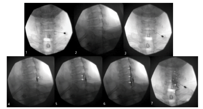
For ease of demonstration, we separated the procedure with CST into seven steps (Fig. 1). The initial three steps involve inserting the needle through the skin and advancing towards the ventral interlaminar line (Fig. 1, Step 1). We use the Ventral Interlaminar Line (VILL) as a radiological landmark beyond which an epidural space may be readily accessed [5]. We recommend that the needle insertion be deep enough that it is “touching” the VILL in order to avoid unnecessary contrast injections (Fig. 1, Step 2). It is also important to confirm the ipsilateral needle location under Anterior-Posterior (AP) fluoroscopy (Fig. 1, Step 3).
Figure 1: Needle navigation; Step 1. A 25 G short-beveled needle is inserted paramedially towards the right C6-C7 interlaminar space under AP fluoroscopy; Step 2. The needle is advanced under CLOF 50 degrees until the needle tip is “touching” the VILL; Step 3. AP position confirms the needle is still on the same side and a few millimeters paramedial for the optimal distribution of the medication; Epidural space identification; Step 4. A small amount (0.2 ml) of Omnipaque 240 was injected under CLOF; Arrows indicate a dorsal (soft tissues) spread; Step 5. Further needle advancement resulting in a qualitative change, when a spread away from the epidural space becomes the spread inside it. Arrows point towards the ventral (epidural) spread; Step 6. Robust epidural spread (arrows) after the injection of 1 ml of contrast under CLOF; Step 7. AP fluoroscopy confirms the epidural spread. Please note the characteristic, uneven, patchy contrast distribution (arrowheads), and opacification of the C8 and T1 nerve roots (arrows)
The next four steps are employed for epidural space identification with CST (Fig. 1). A small amount of contrast (0.1-0.2 ml) is injected with every advancement of the needle, and the resulting images are analyzed (Fig. 1, Step 4 and 5). The needle is advanced until the “breaking point.” The breaking point is the moment in which the spread away from the VILL becomes the spread beyond it (Fig. 1, Step 5). 1 ml of contrast is then injected for the confirmation of the proper epidural spread with CLO and AP fluoroscopy (Fig. 1, Step 6 and 7). This technique is also demonstrated in the cited YouTube video [6].
Results
A total of 1574 patients underwent cervical ESIs with CST. There were no cases of spinal cord penetration, symptomatic epidural hematoma, or Post-Dural Puncture Headache (PDPH). Subdural contrast spread was diagnosed on two occasions by one of the authors and once by the other when they just started practicing CST. PDPH did not develop in the above cases, likely due to the small needle size. There were several accidental intravascular penetrations when we began practicing cervical ESIs with CST. This number decreased significantly when we substituted 25-gauge Quincke cutting-point needles (BD. Franklin Lakes, NJ, USA) with 25-gauge AccuTarg curved tip short bevel spinal needles (Hakko Co., Ltd. Chikuma-Shi, Nagano, Japan). There was one serious complication, unrelated to this technique. The patient developed a hypertensive crisis, severe headaches, and nausea right after the procedure that required hospital admission. Later, the patient was diagnosed with a pseudo subarachnoid hemorrhage based on MRI findings. However, all her symptoms resolved, and the MRI findings cleared the next day.
Discussion
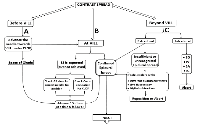
The authors are unaware of previous reports on an algorithm for performing epidural injections with either technique. They could find no reference to it in a computerized search utilizing PubMed, MEDLINE, LILACS, and Embase. The main objectives for the algorithm were to enhance the understanding of this new method, explore possible radiographic scenarios while performing epidural injections with it, and share expertise in clinical decision-making with various image findings. In this algorithm we explored contrast spread based on its relationship with the ventral interlaminar line.
One may recognize contrast spread outside the VILL (Fig. 2A), at the VILL (Fig. 2B), or beyond the VILL (Fig. 2C). When the needle is away from the VILL, one should advance it with the help of contralateral oblique fluoroscopy, until the needle tip is in close proximity to the VILL (Fig. 2A). When performed with proper needle placement and CLOF, there is no need for concern in the majority of injections. The problem here arises when the needle tip appears to be in the desired area, but there is no epidural contrast spread (Fig. 2B).
Figure 2: Algorithm for performing cervical epidural steroid injections with contrast spread technique; VILL: Ventral Interlaminar Line; CLOF: Contralateral Oblique Fluoroscopy; ES: Epidural Spread; CS: Contrast Spread; AP: Anterior-Posterior; SD: Subdural; IV: Intravascular; SA: Subarachnoid; IC: Intracordal; A. Before VILL; B. At VILL; C. Beyond VILL
Possible explanations for this include:
1) Inadvertent contralateral needle placement,
2) Suboptimal angulation of CLOF.
Placement of the needle tip past the midline, at the opposite sagittal plane from the needle’s insertion, may not only decrease the effectiveness of the procedure but may also cause confusion with CLOF. In this case, one should either reposition the needle towards the insertion side or employ ipsilateral oblique fluoroscopy for fluoroscopic identification of needle depth (Fig. 3).
Figure 3: Cervical ESI with contralateral needle placement; Needle was intentionally placed from left to right sagittal plane for demonstration purposes; A. Needle appears deep on CLOF at 50°, and there is dorsal to VILL spread with the injection of 0.3 ml of contrast. Black arrows indicate soft tissue spread outside the VILL; B. AP view confirms needle tip bypassing the midline; C. Ipsilateral view of the same needle placement at 50° obliquity. Note the needle tip by the VILL and contrast dispersal along the ligamentum flavum (yellow arrowheads) after an additional 0.5 ml dye injection; D. Advancing the needle half a millimeter results in epidural spread (white arrows); E. AP view shows the characteristic patchy appearance of the epidural spread at C5 and C6 levels (white arrowheads) and filling of the C8 nerve root (white arrow)
The optimal CLOF angulation for paramedian and median needle placement varies from patient to patient and with different needle trajectories [7]. The authors of this algorithm suggest 50º of obliquity for CLOF when the needle is inserted paramedially (Fig. 1) and 55º of C-Arm rotation when the needle is placed with a traditional midline approach. Compared to paramedian placement, a medially placed needle appears to be deeper with CLOF. This is why more obliquity is necessary. A lower degree of angulation is also acceptable for both approaches; however, in this case, the practitioner needs to understand that the needle appears deeper than it is. In other words, fluoroscopy overestimates needle depth (inverse of a car’s mirror that underestimates the proximity of an object). One may also underestimate needle depth if the angle of CLOF is greater than recommended. For example, more than 55° of C-Arm rotation with a paramedian approach may make the needle appear shallower (just as a car’s mirror underestimates the proximity of the object in its view).
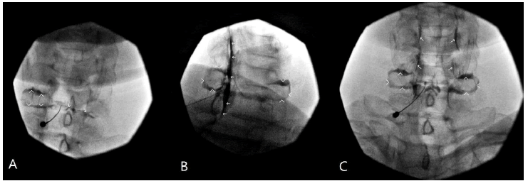
CST increases the chances of Space of Okada (SOO) recognition as, instead of injecting air or saline, it involves the injection of nonionic contrast. SOO was first discovered and described during arthrography that revealed occasional paradoxical communication between contralateral facet joints [8]. Interestingly, SOO fluoroscopic appearance during cervical ESI with CST differs from the original SOO radiological description during facet joint injections [8,9]. With CST, the contrast media is placed along the ligamentum flavum while the needle is advanced towards the epidural space. Whenever the SOO is appearing, the spread is moving towards and around the facet joint, or joints, and resembles an engagement ring, with upper facet joint opacification as the ring stone (Fig. 4). From our experience, in the majority of cases, it is the ipsilateral facet; in a few, it is bilateral, and occasionally, it is only the contralateral joint. In any case, the fluoroscopic opacification of single, or less frequently, bilateral facet joints, is not a complication, but rather an anticipated flow pattern (Fig. 2A).
Figure 4: Contrast dispersal during Space of Okada infiltration while performing cervical ESI with CST; A. AP view. The needle is at the ligamentum flavum but dorsal to the epidural space. There is contrast spread around left C6 facet (arrowheads), and there is an onset of contrast flow towards the right C6 facet (arrows); B. CLO view. The needle was advanced into the epidural space. Note robust epidural spread after 1.5 ml contrast injection (arrows). Also, note the characteristic appearance of the bilateral C6 facets due to the Space of Okada opacification (arrowheads). It resembles an engagement ring; C. AP view. Arrowheads point towards the Space of Okada. Note the characteristic nerve roots appearance with epidural contrast spread (arrows)
Spread beyond the VILL may be either extradural or intradural (Fig. 2C). By “extradural,” we mean spread between the ligamentum flavum and dura. We further divide this spread as either “confirmed epidural spread” or “insufficient or unrecognized epidural spread.” The identification of the proper epidural spread is not always straightforward. There are several accepted epidural contrast spread patterns that the practitioner has to be familiar with to avoid confusion [10]. When the epidural spread is confirmed, inject the medication.
We refer to epidural spread as insufficient or unrecognized when the practitioner cannot accept the quality or quantity of the epidural spread or is uncertain about needle tip location. This usually happens when the contrast spread is insufficient or inadequate to the amount of dye injected. Sometimes this is very subtle and may be picked up only by an experienced eye. Indeed, it may be easily missed, as there are occasional instances of combined partial epidural and intravascular injections. The consequences of intravascular steroid injection at the cervical spine may be catastrophic. If there is any suspicion of vascular uptake, we recommend employing different fluoroscopic views, live fluoroscopy, or digital subtraction (Fig. 2C). When the epidural spread is confirmed, proceed with injection. However, if intravascular uptake is recognized, withdraw the needle, and reposition or abort.
The intradural or intrathecal spread may be:
1) Subdural, between the dura and arachnoid mater,
2) Intravascular, into arachnoid mater,
3) Subarachnoid, into the spinal fluid,
4) And even intracordal.
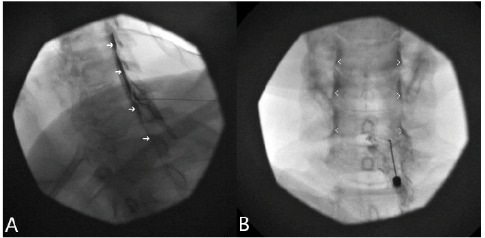
One of the intentions of this algorithm is the prevention of subdural needle penetration. It is not always easy to differentiate between epidural and subdural spread. Epidural space is small at the cervical level, and 1-2 ml of contrast may spread to multiple levels. Indeed, this is similar in appearance to subdural spread. Epidural spread may frequently present as a thin line in the posterior epidural space with lateral and CLO fluoroscopy and thus mimic subdural spread.
However, there are some distinctions: Typically, the contrast outlines the nerve roots in epidural, but not in subdural spread. This is why epidural spread presents as intermittent waves, with a characteristic “seagulls” appearance (Fig. 5). In contrast, subdural spread presents as straight parallel lines, with a characteristic “railroad” or “tram track” appearance. Epidural spread is commonly limited and spreads at a few levels. However, subdural spread is usually wide and spreads to multiple levels. It is important to note that subdural injection patterns may vary, and discussing all the possible variations is beyond the scope of this article.
Figure 5: Cervical epidurogram mimicking subdural spread; A. Robust epidural spread after 1.5 ml contrast injection under 50° CLOF. Note the wide contrast flow (arrows) resembling subdural spread; B. AP epidurogram confirming epidural spread. Note bilateral uneven intermittent spread (arrowheads) resembling “waves” or “seagulls” that results from the contrast filling up the nerve roots. However, this is different from a subdural spread that appears similar to straight “pipes”
The main theoretical advantage of CST is that it decreases the chance of subdural needle placement by bringing the practitioner’s attention to contrast spread. Unlike LORT, where the goal is to achieve LOR, with CST, the aim is to explore the resulting image on the screen. So, whenever the spread outside of the VILL (or epidural space) becomes the spread beyond it, needle advancement ceases. One should evaluate the quality of the epidural spread and follow the recommended steps of the algorithm (Fig. 2C).
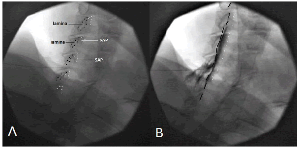
Unexpected dural puncture or even spinal cord penetration can occur despite seemingly proper needle placement. This may happen when the physician misinterprets the Superior Articular Pillars Line (SAPL) for VILL. Similar to VILL [5], SAPL is a hypothetical fluoroscopic landmark, but instead of ventral laminar, it outlines superior articular pillars (Fig. 6). It is critical to understand the differences between these two lines to prevent accidental deep needle penetration.
Figure 6: VILL vs. SAPL; A. The needle is approaching VILL under 50° CLOF. Black dots silhouette ventral laminas. White dots demarcate the margins of the superior articular pillars; B. Omnipaque 240 1 ml was injected epidurally. Note the contrast media spread ventral to the VILL (black dashed line) and dorsal to the SAPL (white dotted line)
However, despite some theoretical and practical advantages, CST is not a time-proven method for epidural space recognition, loss of resistance is. Multicenter clinical trials are warranted for the exploration of its utility in clinical practice.
Conclusion
The ultimate goal of any injection is the safe delivery of medication to the targeted area of pathology. This is especially important at the cervical spine where spaces are small, and the probability of serious complications is high. Utilization of contrast media for needle depth visualization, along with a knowledgeable interpretation of the fluoroscopic images, may decrease risk, improve the quality of the procedure, and enhance both patients’ and physicians’ satisfaction with fluoroscopy-guided interlaminar epidural injections.
Acknowledgement
We want to thank Md Ahmed for his assistance in image-editing and designing the algorithm, and Spiros Poulakos for editing the video. We would also like to acknowledge Luisa and Bernadette, our fluoroscopy technicians, whose everyday dedication to work made this research possible.
Disclosure and Conflict of Interest
There is nothing to disclose, and there is no conflict of interest for any of the authors.
REFERENCES
- Perper Y.: Contrast spread technique. Pain Med. 2015;16:827-828.
- Perper Y.: Contrast spread technique: evolution. Pain Med. 2016;17:1385-1386.
- Whitworth M.: Puttlitz line: A rapid and reproducible fluoroscopic needle endpoint for cervical interlaminar epidural steroid injections. Pain Med. 2008;9:136-137.
- Furman M., Jasper N.R., Lin H.W.: Fluoroscopic contralateral oblique view in interlaminar interventions: A technical note. Pain Med. 2012;13:1389-1396.
- Gill J., Aner M., Simopoulos T.: Intricacies of the contralateral oblique view for interlaminar epidural access. Pain Med. 2013;14:1265-1266.
- Perper Y.: Contrast spread technique: Evolution. Pain Med. 2016;17:1385-1386.
- Park J.Y., Karm M.H., Kim D.H., et al.: Optimal angle of contralateral oblique view in cervical interlaminar epidural injection depending on the needle tip position. Pain Physician. 2017;201:169-175.
- Okada K.: Studies on the cervical facet joints using arthrography of the cervical facet joint. Nihon Seikeigeka Gakkai Zasshi. 1981;55:563-580.
- Murthy N.S., Maus T.P., Aprill C.N.: Retrodural Space of Okada. Am J Roentgenol. 2011;196:784-789.
- Gill J., Nagda J., Aner M., et al.: Cervical epidural contrast spread patterns in fluoroscopic antero-posterior, lateral, and contralateral oblique view: a three dimensional analysis. Pain Med. 2017;18:1027-1039.




 Journal of Orthopaedics Trauma Surgery and Related Research a publication of Polish Society, is a peer-reviewed online journal with quaterly print on demand compilation of issues published.